
International Directional Services
International Directional Services (IDS) offers expertise for borehole deviation surveys and directional drilling services in the mineral, energy, and civil markets. IDS provides its customers with five product and service lines: downhole deviation surveys, directional drilling services, downhole instrumentation sales and rentals, directional mud motor sales, and borehole geophysics in select international markets.

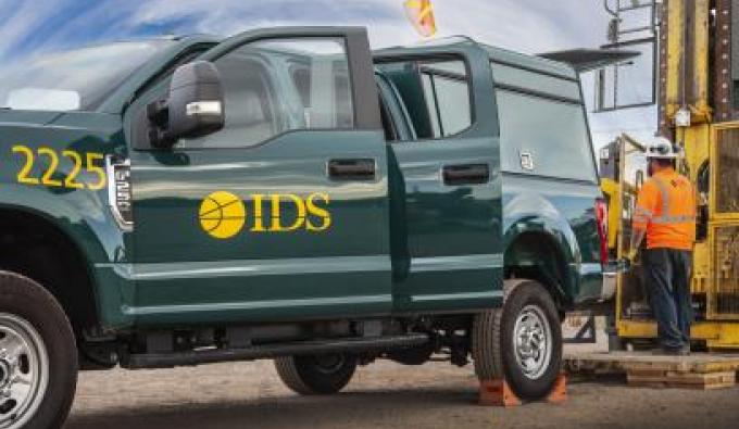
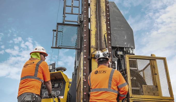
IDS brings over 50 years of experience delivering global directional drilling programs. Our team of experts provide strategic planning and precise execution of programs to reach targets for mineral exploration, coal degasification and civil infrastructure projects. IDS delivers consistent performance and precision in directional drilling projects at exceptionally competitive rates.
IDS delivers accurate and reliable borehole deviation data. We employ robust down-hole survey technology, versatile tools and solutions for drill programs. We offer professional verification of borehole deviation data. Our solutions are tailored to specific needs, including importing Gyro Data directly into mine design modeling programs.
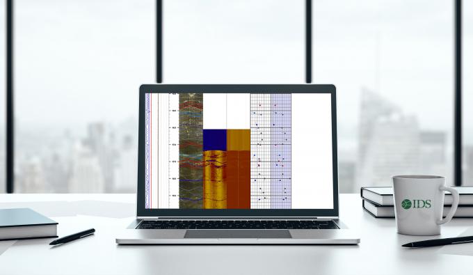
IDS is a leading provider of borehole geophysical logging services in select international mining and civil construction markets. Logging parameters include, but are not limited to: optical and acoustic televiewer, caliper, electric logs, magnetic data, natural gamma, fluid flow and resistivity/conductivity, video.
IDS provides the latest rental surveying tools and technology in the industry: Veracio, Stockholm Precision Tools, and Minnovare Azimuth Aligner® North-Seeking Gyro Rig Alignment System.

Quality Assurance
IDS maintains a rigorous QA/QC program for delivered data quality including employee training programs, routine data reviews, and instrument calibration facilities and protocols. IDS’s technical expertise provides customers with a robust QA/QC program for data collected by both IDS and other providers.
As an industry leader in directional drilling technology, IDS offers a variety of proven directional drilling products to contractors and resellers including, directional drilling motors, non-magnetic drill rods, directional drill bits, and accessories.
